DI security on the GenX network
This section describes the DI security approach for deployments on the GenX network.
Network security
Gen5 Riva devices operate on an AMI network that consists of the following:
-
Mesh network composed of clusters of Wi-SUN FAN profile-compliant wireless networks that are founded on the IEEE 802.15.4g and IEEE 802.15.4e standards. This provides for wide geographic area network services that are owned and managed internally by the utility.
-
WiMAX network provides the data backhaul technology of choice for mesh networks. WiMAX is a point to multipoint technology providing broadband data services and exceptional quality of service.
The network is fault tolerant in design and topology and is multi-tenant in nature, meaning that multiple applications are expected to share the same communication infrastructure. The multi-tenant nature of the network drives the necessity to implement the network with proven, reliable, and efficient end-to-end message priority forwarding protocols.
The DI ecosystem utilizes the security infrastructure, policies, procedures, and methodology of the AMI network. Security is built into the Itron technology with secure data transmission at all layers, protecting data between the back office and the Itron devices. The following describes what Itron protects and how:
-
Application traffic flowing across the network. End-to-end layer protection provides a secure association for all back-office controls and applications that send commands to the device. X.509 certificates with encoded roles enable a secure association to occur between both ends. Unique key pairs are formed for each secure association and keys for each link are automatically renewed regularly, with key renewal staggered across the network. The data hash-based message authentication code (HMAC) with SHA-256. Devices in the field use public keys to verify firmware authenticity and integrity at boot time and periodically at run time.
-
Firmware upgrades sent from the back office. Firmware code-signing ensures that all firmware images released by Itron have a digital signature. The device uses public key cryptography for verifying firmware. Each firmware load is digitally signed, encrypted for Gen5 Riva, and verified before control is transferred. Without the private key (which is stored securely by Itron on its premises) to sign the firmware, no valid firmware can be created by an intruder or loaded on to the device for boot-up.
-
Wide area network (WAN) backhaul. IPSec protection over WAN is enabled by securing access from the backhaul network. A VPN tunnel is created with a static key, hashed, and filters are applied to the tunnel to pass only the intended traffic.
-
Network communications within the RF mesh. Link layer security with EC-based certificates and HMAC SHA-256 ensures that a device is not allowed to participate fully in the RF mesh until it has been authenticated by the back office.
-
Critical commands. Critical Operations Protector (COP) is a hardware-based security policy enforcement mechanism to prevent the misuse of critical control commands.
-
Access by external devices. Itron uses Public Key Infrastructure (PKI) with a managed Certificate Authority (CA) for digital certificate management with standards-based X.509 certificates. Role-based access control is built into the endpoints.
-
Certificates and keys. Hardware security modules (HSMs) protect certificates and keys. Cryptographic key management rules are enforced to assure the security of the contents of the HSMs. Located in the back office, HSMs provide FIPS 140-2 level 3 compliant secure key storage and help establish secure connection to meters in the field. The HSM with KeySafe enables a “Configure and Forget” policy enforcement that cannot be bypassed like software because it is smart-card-based with multi-party control.
-
Network access. Link layer security is achieved with Driver’s License Certificate Authority (DLCA), which issues a driver’s license to each node that is allowed to participate in the network. FSU-SAM, FDM Tools, and Field Tools enable Field Service Units (FSUs) to be personalized with appropriate roles for authorized access.
-
Physical security of field devices. As field devices are out in the open and accessible to physical tamper, Itron’s security approach eliminates the possibility of a network-wide wholesale attack by restricting any possible threat to the breached device. Board-level security techniques include restricting access to flash pins, securing key port limiting access to sensitive key materials in the chip, and denying access to credentials that are stored in the secure memory.
Itron uses standard cryptographic algorithms, hardware security techniques, and operational best practices to ensure end-to-end security in the system. For example:
-
Application traffic flowing across the network is protected with end-to-end app-layer protection and KeySafe (AES-256, HMAC SHA-256)
-
Firmware upgrades sent from the back office are protected with firmware code signing EC-P256 (ECDSA with SHA256)
-
Network communications within the RF mesh are protected with link layer security (EC-based certs, HMAC SHA-256)
-
Access by devices (including external tools) is protected with PKI-based authentication and authorization (EC-based certs)
-
WAN backhaul is protected with IPSec over WAN
-
User-initiated traffic to and from applications is protected with role-based access control (CAAS).
The following cryptographic algorithms are used throughout the system:
-
Public key cryptography
-
EC-X9.63 for signing certificates used for authentication throughout our system and for signing keying material
-
-
Symmetric key cryptography
-
AES for encryption
-
Keyed-HMAC-SHA 1 and HMAC-SHA256 for data integrity checks
-
-
Key agreement
-
DH and ECDH
-
Internet Key Exchange (IKE)v1 for IPsec transport on WAN backhaul links that typically involve a public carrier
-
-
Digital identity
-
X.509 digital certificates
-
Cryptographic message syntax
-
-
Web security – HTTP over TLS (RFC 2817, 2818)
-
Includes key negotiation and data protection
-
With client certificates, performs mutual authentication of both ends (currently, SSL/TLS connections are used in the back office)
-
-
Protection of sensitive material in the Itron security system (specifically, the private keys used within the system)
-
Optional hardware security module (HSM) such as FIPS-140 level 3 compliant smart cards or servers and other hardware technologies
-
Procedural rigor (secured perimeter, two-man requirements)
-
-
Key management tools and practices
-
Periodic key rollovers
-
Security event monitoring
-
Support for certificate revocation lists (CRL)
-
Multi-party control for sensitive operations and control commands, typically enforced using smart cards
-
For more information about GenX network security, see the latest GenX Security Operations Guide and GenX Security Overview on products.itron.com.
Gen5 Riva electricity meters (HW 4.2)
Tamper detection is a primary physical security method. The Gen5 Riva meter reports all tampering attempts to the network. The following tamper events are defined:
-
Magnetic Tamper Detect
-
Outage
-
Reverse Energy
-
Inversion Tamper
-
Removal Tamper
DI agents operate within the Linux userspace, using typical Linux userland/kernel separation to isolate the DI agent and disallow the agent from modifying the kernel or other processes, and using additional mechanisms to isolate the system as a whole from the agents.
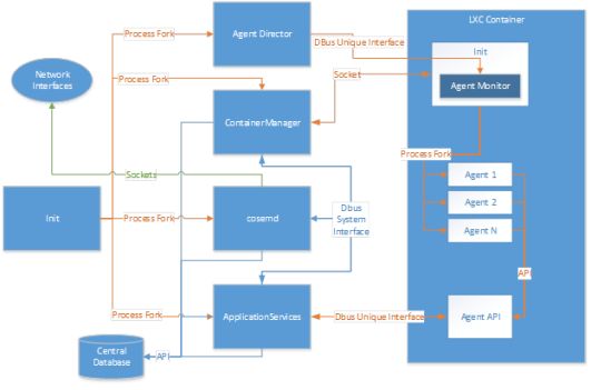
DI agents operate within a container. The ContainerManager uses unprivileged LXC containers, meaning they are not run with root privileges on the host side. When a container is started, lxc-start runs in the host’s PID namespace, as containerd_u. The processes inside the container run in that container’s PID namespace as the root user in the container.
Users in the container (including root) are mapped as subordinate user IDs of containerd_u on the host. Groups in the container are mapped as subordinate group IDs of containerd_g. If a user were to break out of the container, it would operate as containerd_u, and be unable to elevate its own privileges.
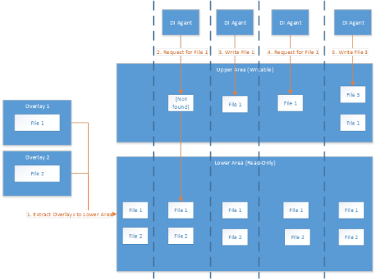
Each container built by ContainerManager is constructed out of a series of ‘overlays’ – sets of files that make up discrete components to be included within the container. The base set of files required for running a binary make up one set of overlays. An agent package may contain one or more other of these overlays containing required files. The central database contains information about which overlays are used to build each container.
During container construction, the container sets up an overlay filesystem (OverlayFS). The lower, or read-only, part of the filesystem is where ContainerManager puts the files corresponding to each configured overlay. The upper, or writable, part of the filesystem by default does not contain any file. From the point of view of a DI agent, these two parts of the filesystem are viewed simultaneously, and the agent is not able to determine what is in the read-only part of the filesystem and what is in the writeable part. When a DI agent attempts to read a file, the filesystem first tries to serve the file from the upper part of the filesystem. If the file does not exist, it then serves the file from the lower part of the filesystem. However, when a DI agent tries to save a file, it always saves to the upper part of the filesystem. It is never synchronized to the lower part. Subsequent attempts to read the file returns the copy saved to the upper part, but the lower copy is never modified. In this way, the files associated with an overlay are preserved. Modifications to these files are only performed within the context of a single run of a single container.
When the container is shut down, all files stored in the upper filesystem are destroyed. If an agent required non-volatile storage, it must request access to flash.
The ContainerManager supports using seccomp files to provide restrictions to which interfaces into the kernel a container may use. This allows specification of the list to either allow or restrict on a per container basis. Itron firmware provides an initial set of default options, but these may be overridden on a per-container or per-overlay basis. Such an override must be specifically requested when submitting for certification and signing, which allows the certifier to accept or reject the override request.
All agent data (events & alarms) passes exclusively via the ApplicationServices (AppServ) component (with the exception of the HAN 2030.5 agent). AppServ primarily acts on an interface between all installed DI agents and the Riva 4.2 system. AppServ sits outside the containers where Agents are installed. But there are AppServ APIs within both containers that communicate only to the AppServ component, via DBUS. The calls these AppServ APIs can make are highly restricted and do not allow agents to transmit data outside of containers without going via AppServ.
One of AppServ’s functions is to govern the amount of data that is passed from agents to the endpoint’s database. It does this via the policy file that is included with each agent package. Policy files are scrutinized and validated during the agent certification process. All installed agents either use data values from their policy file, or if no policy file was included, default data limits of 15kB of data and 10 alarms per 24-hour period are used instead. The main intent of the policy file is to prevent a single agent from consuming the entire data allowance of an endpoint and flooding the network with data.
The policy file stipulates how much data an agent is intending to produce and transmit within any given 24-hour period. The policy file includes all communication channels (for example, Mesh or P2P), and each channel has independent daily limits. During typical operation, AppServ passes all agent event data into the database, for later retrieval via interrogation reads. However, if an agent meets its daily data limit, AppServ no longer passes the data into the database, and instead responds to the agent with a data limit error and rejects the data. It is up to individual agent logic how rejected data is handled.
Interrogation reads are controlled by the utility. At the time of an interrogation read request, including DI Data, the endpoint tags all agent event data as DI Data and includes it within the interrogation read response. After data is sent, it is flagged in the database as sent, and is not included in future interrogation read responses. However, it can still be accessed locally and via contingency reads.
Agent alarms are also passed through AppServ. But AppServ recognizes the data as real-time agent alarms and they are forwarded immediately to the endpoint comm module for transmission. The policy file also includes a daily limit for gent alarms. After this limit is met, AppServ no longer forwards alarm data to the comm module. The intent of limiting alarms is to prevent rogue or ‘runaway’ agents from flooding the network with alarms. As with rejected agent data, it is the responsibility of the individual agents to handle rejected alarms.
Wi-Fi
Itron uses off-the-shelf Linux Wi-Fi drivers provided by Texas Instruments for use with the integrated Wi-Fi module. These drivers are integrated directly into the Linux kernel. The driver and the chipset support maintaining two simultaneous Wi-Fi connections (for example, connecting to two APs simultaneously or connecting to an AP while also connecting to a Wi-Fi direct group). Within the operating system, the one hardware device appears as two Wi-Fi interfaces.
The first Wi-Fi interface (Interface 1) is used exclusively by FDM Tools. FDM Tools uses the meter’s Wi-Fi to support the sending of local commands to the device. To provide this functionality, FDM Tools uses Windows 10 on the host laptop to create a Wi-Fi Direct legacy mode network. This network uses an SSID and PSK generated from the system title of the specific meter to which it wants to connect. The meter is set up to listen for advertisements from this specific SSID and attempts to connect when detected.
Once the network is connected, FDM Tools sets up a TLS session. This requires a smart card (the FSU) that protects the FDM Tools client private key and limits the number of sessions the key can be used to establish TLS sessions. Also, a firewall is in place (iptables) that limits which ports are open. The TLS session is established prior to a secured DLMS/COSEM exchange with the meter.
The second Wi-Fi interface is exclusively used for DI. This interface is disabled by default: it does not exist and therefore cannot send or receive data. It can be enabled through either FDM Tools directly or through the portal and HCM, and upon being enabled it must be configured to operate in one of two modes:
-
Client mode. In this mode, the meter connects to a customer's AP. The SSID and passphrase for the customer's AP are passed to the meter through FDM Tools or the portal + HCM.
-
AP mode. In this mode, the meter provides an AP to which a customer device can connect. Credentials are created by the meter and provided to the configuring tool (FDM Tools or the portal + HCM), which can then be provided to the customer, allowing them to connect their device directly to the meter.
After the second Wi-Fi interface is enabled, configured, and connected, DI can use this connection in a limited fashion.
Network interfaces are not directly available inside containers for use by DI Agents. However, it is necessary and required for developers to be able to use POSIX-compliant network calls when implementing agents that need to access the Wi-Fi for HAN purposes. To support this need without giving direct access to a network interface inside the container, which would require giving access to a physical network device, the meter creates a bridge interface that is accessible inside the container. This bridge interface is separately firewalled from other network interfaces. However, when the HAN Wi-Fi network is available, traffic on certain ports is forwarded between the HAN Wi-Fi network and the bridge interface. The specific ports that are forwarded are requested by the DI HAN Agent (isolated in its own container) at certification time and then bundled into the installation package. No other agents or containers have direct Wi-Fi access.
Using this bridge interface paradigm allows the meter to limit DI Agent network usage to only the ports that are required. It also allows fine-grained control over the throughput of messages sent over this interface: firewall forwarding rules support the implementation of specific bandwidth limitations over arbitrary time periods on specific ports.
HAN (2030.5)
The meter can utilize the second Wi-Fi interface described in the preceding section to provide home area network (HAN) functionality via the IEEE 2030.5 protocol to any device joined on the same network.
IEEE 2030.5 defines a method of authentication that depends on server and client certificates. Here, the “server” is the meter, and the “client” is the smart phone. The DI HAN Agent and the IEEE 2030.5 client use mutual TLS to authenticate. The keys used are retained internally to the respective meters and are not used with any other meters. If no TLS session is in place, a TLS handshake occurs between the client and server:
-
Authentication of the server is part of the TLS handshake by validating its device certificate as described in (IETF RFC 5246), Section 7 using the inherent PKI. If security policy dictates, additional certificate validation may be required.
-
If the client has a device certificate, authentication of the client is part of the TLS handshake by validating the client’s device certificate as described in (IETF RFC 5246), Section 7 using the inherent PKI. If security policy dictates, additional certificate validation may be required. The authentication level to be compared with a resource’s corresponding AuthType attribute is 0x8 (device certificate).
-
If the client has a self-signed certificate, the self-signed certificate SHALL is validated for correctness. The authentication level to be compared with a resource’s corresponding AuthType attribute is 0x4 (self-signed certificate).
If the client does not have a certificate and the security policy allows, client authentication may not need to take place, or secondary client authentication may take place after the TLS handshake. The HAN PKI uses a device certificate provided at manufacturing time for the server, and a device certificate provided to the client. Utilities are responsible for providing a device certificate to the client and or choosing to use a self-signed certificate. In either case, the client’s long-form device identifier (LFDI) is to be provided to the meter as part of the provisioning process. The client device certificate is the certificate and key held in the smart phone app.
Encryption of data transmitted to and from the home area network is via TLS as per 2030.5 specification. 2030.5 requires 128-bit block cipher security and TLS 1.2 at minimum. Link-layer network protection is provided by WPA2.
DI Data Cloud
The DI Data Cloud is a centralized service designed for edge application developers who want to stream edge application data to their back office over a consumer's Wi-Fi. The service enables any DI agent to push data payloads generically through an AppServ API to the meter's Wi-Fi radio to a preconfigured cloud target over the public internet. Multiple subscribers can subscribe to these data feeds through Data Hub. It's different from HAN, which is for communicating with devices within the home using the 2030.5 protocol and is contained within the local Wi-Fi network.
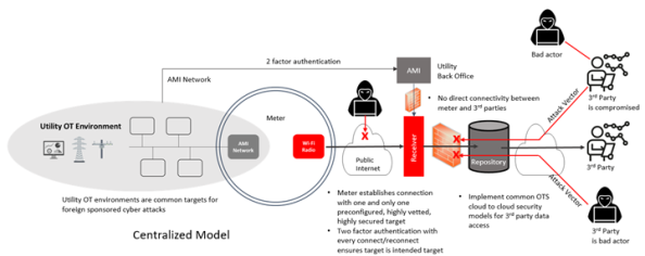
For the productization of the DI Data Cloud, there is a focus on minimizing OT Network Security Risks with a Centralized Model, which presents a smaller attack vector versus the Direct Upload Model. This involves the meter establishing a connection with only one target receiver over the public internet, which is preconfigured in the meter. Two-factor authentication ensures connection only with the intended target, and the meter refuses or is incapable of establishing any other public connection. The target receiver is highly vetted, secured, and audited, with third parties connecting to the repository but having no connection to the receiver or meters, thus presenting no attack vectors between third parties and meters.
This centralized model minimizes OT network security risks in the following ways:
-
Edge applications can only communicate outside their container through an abstraction (AppServ)
-
Data received at the API is treated as an opaque piece of binary data. The API does not evaluate the data payloads but forwards them intact to downstream subscribers.
-
Meters can establish a connection with one and only one target receiver over the public internet
-
The target is preconfigured in the meter
-
Multifactor authentication ensures connection only with the intended target
-
The meter is incapable of establishing any other public connection
-
-
Target receiver is highly vetted, highly secured, highly audited
-
Third parties connect to the repository. Because third parties have no connection to receivers or meters, there are no attack vectors between third parties and meters
-
Typically accepted cloud-to-cloud security models implemented between third parties and central repository
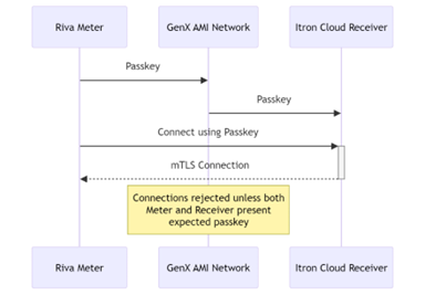
The multifactor authentication works as follows:
-
The meter creates a unique passkey and random ID. This data is securely provided to Itron headend system (and ultimately, the Itron Cloud Receiver) via the AMI network. The unique passkey is later used as a second factor when the meter authenticates the Itron Cloud Receiver. The random ID provides a means of anonymizing transit data sent from the meter to the Itron Cloud Receiver.
-
The meter creates an mTLS 1.2 or higher connection using an RSA algorithm with a 2048-bit key length and PKCS#7 padding scheme to the static IP address of the Itron Cloud Receiver. The certificate's trust anchor must be itron.com, and the static IP address of the Itron Cloud Receiver must be hardcoded in the meter’s firmware.
-
The meter calls the auth challenge endpoint with its random ID and a nonce.
-
The Itron Cloud Receiver responds by using the meter secret to create a hash of a salt and the nonce.
-
The meter validates that it can decrypt the response using the secret and that the nonce is the same one it sent.
-
ElectronicSerialNumbers of devices are never sent in the payload transmitted from the meter to the Itron Cloud Receiver. The meter generates a random identifier sent with the passkey to the Itron Cloud Receiver over the AMI network. The metrology payload contains the ID the receiver uses to correlate the data with the correct ESN.
Peer-to-peer
DI supports peer-to-peer (P2P) communications, allowing individual electric meters to communicate securely with each other. The peer-to-peer communications can be either Power Line Carrier (PLC) or RF. This local communication does not require all messages to be routed through the APs, which provides a lower latency message transfer for the DI applications. In addition to communications, meters can store details of their neighbors locally and collect statistics and information, such as link quality for troubleshooting purposes. Peer-to-peer communications are bound by bandwidth limitations that prevent the communications interfaces from being overwhelmed with messages. These bandwidth limitations are provided by per-agent policies, and enforced by the meter
All Itron meters support PKI when operating on the FAN. During manufacturing, meters are loaded with a unique X.509 meter certificate. This is used with the PKI to ensure secure communication over the FAN.
All P2P messages, regardless of medium or point of origin, are secured with application layer encryption using per-customer unique symmetric keys that are not used for anything else. These keys are generated from material on the device plus customer-specific information plus information known only to the signed and encrypted package. Itron cannot generate it. The algorithm used for encryption is AES-256-GCM.
On a GenX network, P2P supports:
-
RF unicasts (Global and Link-local)
-
PLC broadcasts
-
Common periodic
-
Immediate
-
-
No AMI communication
-
DI P2P messaging does not have link-layer security